Inquirer:-
We did welding LCS to SS 316L by using SS 309L. Weld Metal We checked with PMI Machine, We found it to be of SS 308 compositions. How it is possible? , Kindly clarify it. The process used was GTAW.
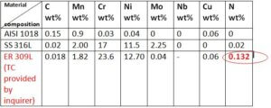
The chemical composition of the AISI 1018 Steel, ASTM A 240 Type 316L Stainless Steel base metals, and AWS A 5.9 309L Filler metal (Test Certificate) provided by the inquirer is as shown in Table 1.
Table 1:- Nominal chemical composition in wt% of the base metal and filler metal (client’s consumable supplier Test Certificate) Certificate.

*only elements applicable for Cr eq & Ni eq are tabulated here.
Answer:-
Dear Sir,
You are using the right kind of Filler Metal- E/ER 309L that can be used to successfully join AISI 1018 Steel and Type 316L Stainless Steel using the GTAW Process.
When your Filler Metal composition is double-checked with SFA-5.9/SFA-5.9M specification covered under ASME SEC II Part C, All alloying elements were found within the specification range, Except Nitrogen, which did not match with the 5.9/SFA-5.9M specification standard. The difference in Nitrogen concentration in your purchased consumables might be easily detected.. i.e Your TC is showing Nitrogen content as 0.132 %Wt. Which is very undesirable with respect to the hot cracking susceptibility of the weld metal
For reference, the chemical composition of the ER 309L covered under SFA-5.9/SFA-5.9M specification mentioned in Table 2 with reference to ASME SEC II Part C Specifications for Welding Rods, Electrodes, and Filler Metals
Table 2 chemical composition of filler metal composition (in Wt%)

Note that the above specification does not specify Nitrogen content in the filler metal composition.
Later, I will try to explain the effect of “uninvited” Nitrogen content (in your ER 309L Filler Metal composition) on the dissimilar CS to 316L joint Weld Metal Ferrite content, i.e., Ferrite Number (FN), final mode of solidification, and thus solidification tendency as a function of the above two parameters by demonstrating the Analysis on WRC-1992 diagram.
But in order to appreciate, the SFA-5.9/SFA-5.9M specification, we will first understand what is called a “Safe Weld Metal Composition”. That does not contain any risk of hot cracking! using the analysis on the WRC-1992 diagram. In order to do this exercise on the WRC-1992 diagram, LET US FIRST EMPLOY THE STANDARD ER309L CONSUMABLE COMPOSITION AS PROVIDED IN TABLE 2.
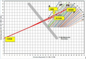
When the composition of the Creq, Nieq of the base metals, filler metal (Standard Composition) are plotted on the WRC-1992 diagram and considering the 30% dilution (equal 15% from CS & 15% from SS 316L side), using low heat input in GTAW process, We may obtain minimum 3.5 FN with FA mode (Primary Ferrite and Secondary Austenite) mode of solidification, which is very “Safe” composition to avoid Hot cracking tendency. See between two thick Green dashed lines.
(Thick-dashed lines are boundaries indicating the mode of solidification and iso-ferrite lines are inclined click-wise showing the FN)

Fig. 1 CASE-I AISI C1018 – SS 316L weld joint using ER 309L Analysis on WRC-1992 considering 30% dilution of the filler metal.
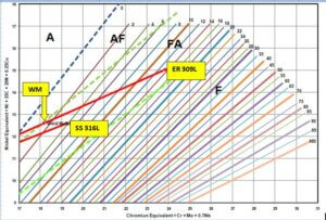
Short-Axes view for better visibility of the Weld Metal composition is shown below in Fig. 2:-

Fig. 2 Short-Axes view of Fig 1 Case-I
Since, you are using the GTAW process, which is a manual process, so, the dilution of base metals into the Filler metal composition may be varying from 15-20%. So, considering the total 40 % dilution of the ER 309L Filler Metal ( 20-20% from each base metal). You may still obtain min 1.5 -2 FN and AF Mode of solidification (Primary Austenite and Secondary Ferrite), which is a rather safe composition that may or may not avoid hot cracking. See in the Short-axes graph below

Fig. 3 CASE-II AISI C1018 – SS 316L weld joint using ER 309L Analysis on WRC-1992 considering 40% dilution of the filler metal.
But to avoid any risk of Hot cracking in Weld. The better practice is to keep Low H. I as much as the possible and second trick is to offset the welding arc so that most of the arc heat falls on the SS 316L base metal side and less on Carbon Steel Side, which will reduce the dilution of carbon and other alloying elements into the filler metal composition. In that case, considering 10% dilution from CS into Filler metal composition and rest, 20% from SS 316L into filler metal composition, We may comfortably get around 5-6 FN and FA mode of solidification which is without any risk of hot cracking of weld metal. Respective weld metal position on WRC-1992 diagram as shown with this short-axes graph represented as CASE-III

Fig. 4 CASE-III AISI C1018 – SS 316L weld joint using ER 309L Analysis on WRC-1992 considering 10% dilution from CS and 20% dilution from SS 316L into ER309L filler metal composition.
Now, let us turn back to our main point of discussion, the effect of Nitrogen on weld metal chemistry of CS-SS weld joint.
By plotting the composition of the base metals and Filler Metal composition (As Per your Supplier’s TC -Mentioned in Table 1), the respective position of the weld metal compositions can be shown as in Fig 5.
Below is the same kind of analysis showing that as low as 0.132% of Nitrogen, even with low H.I and thus with only 30% dilution of filler metal can literary “Push” the weld metal composition towards A-Mode(Austenite mode ) solidification with very fewer traces of ferrite. This means This situation will compel the weld metal composition to undergo solidification in fully austenitic mode and/or austenite-ferrite but with very little or no ferrite. This ferrite-free composition is a highly undesirable composition often threatening to the life of the weld metal. See below analysis of WRC-1992 Short-axes graph. Using the Test Certificate chemical composition of the filler metal as provided by the inquirer.
This is because; Nitrogen is a strong austenite stabilizer so weld metal ferrite content (FN) reduces dramatically with a very minute amount of Nitrogen dilution from the filler Metal into Weld Metal. To add in that Carbon is also a strong austenite stabilizer like Nitrogen and that could be also diluted from AISI C1018 Steel into filler metal so, this combined effect of Carbon & Nitrogen can leave Weld Metal composition into very “unsafe” condition !.

Fig. 5 Special Case: – Weld Metal composition analysis on WRC-1992 diagram using the chemical composition of the Filler metal provided by the inquirer.
Besides using the PMI instrument, I would advise you to use Fischer TM Make, Ferritoscope instrument, calibrated with AWS A4.2 to better check weld metal composition experimentally.
Secondly, if the application of your weldment is in a Corrosion environment, you are advised to use ER309LMo filler metal containing 2-3 Wt% Molybdenum content to obtain resistance to pitting corrosion in service.
Follow-up. The inquirer was advised to re-confirm the chemical composition of the filler metal from another third-party laboratory.
Welding Consultant,
Weld Met Advisory Services

